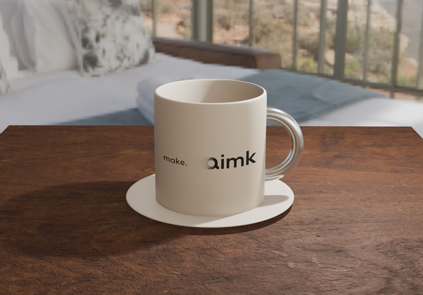
In the previous article, Blender Texture Basics: Base Color, Roughness, and Normal Maps, we put textures on a wooden table. This time we'll put a logo on the front of a coffee cup, and cover UV unwrapping — how you decide where an image sits and which way it faces.
Blender can unwrap UVs automatically, but that alone won't put an image exactly where you want it. We'll try the automatic unwrap first and see how far it gets us. From there we'll look at how to adjust the UVs so the image lands where you intend.
* This article was verified with Blender 5.2 LTS.
Opening the UV Editor
UVs are the information that decides which part of an image goes where on the model. Position is expressed as U across and V up, generally in a range of 0 to 1. The screen where you view and edit that layout is the UV Editor.
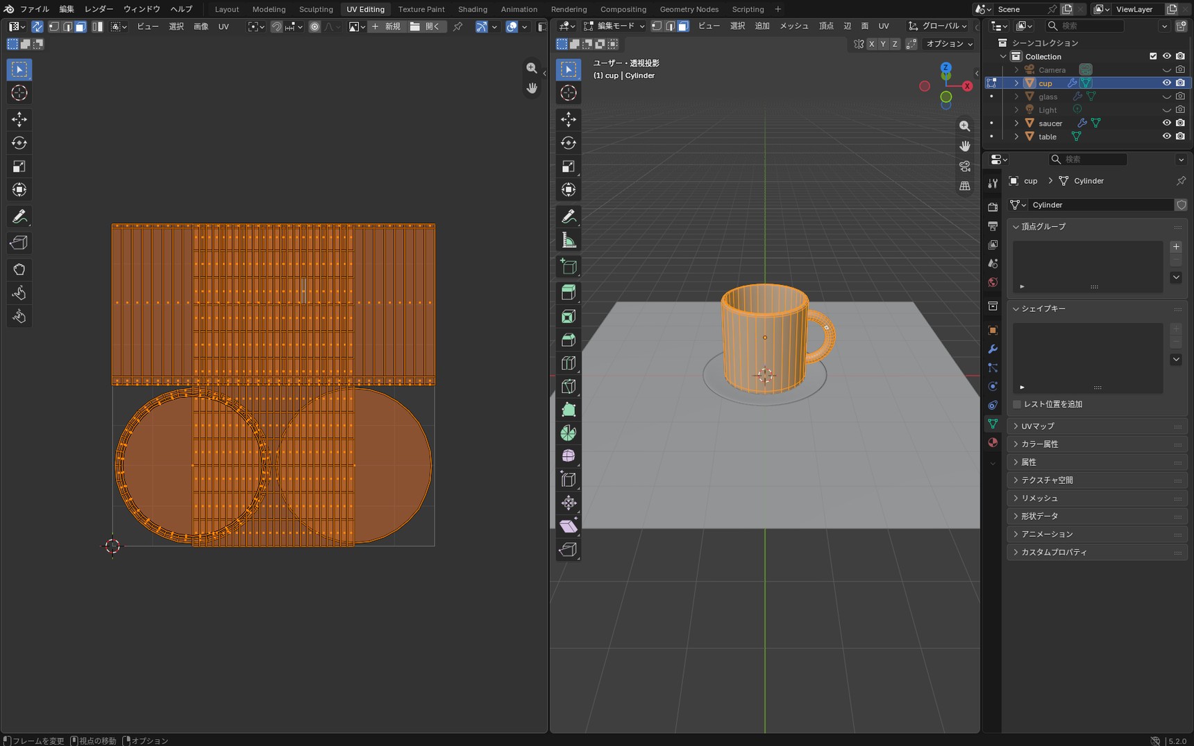
Pick "UV Editing" from the tabs at the top of the screen. The screen splits in two, with the UV Editor on the left and the 3D Viewport on the right.
Select the cup in the 3D Viewport and press Tab to enter Edit Mode. The UVs appear in the UV Editor.
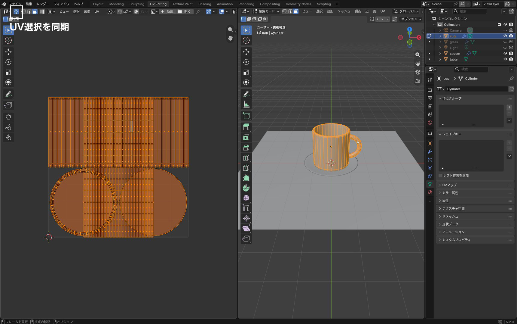
"UV Sync Selection" changed in Blender 5.0
In earlier versions of Blender, "UV Sync Selection" at the top left of the UV Editor was off by default. With it off, only the UVs for the faces selected in the 3D Viewport are shown.
From Blender 5.0 onwards, this setting is on from the start. That means all the UVs are shown even when nothing is selected in the 3D Viewport. It looks different from before, but there's no need to change it.
Unwrapping automatically with Smart UV Project
Blender has a feature that builds UVs automatically, called "Smart UV Project". Let's try that first.
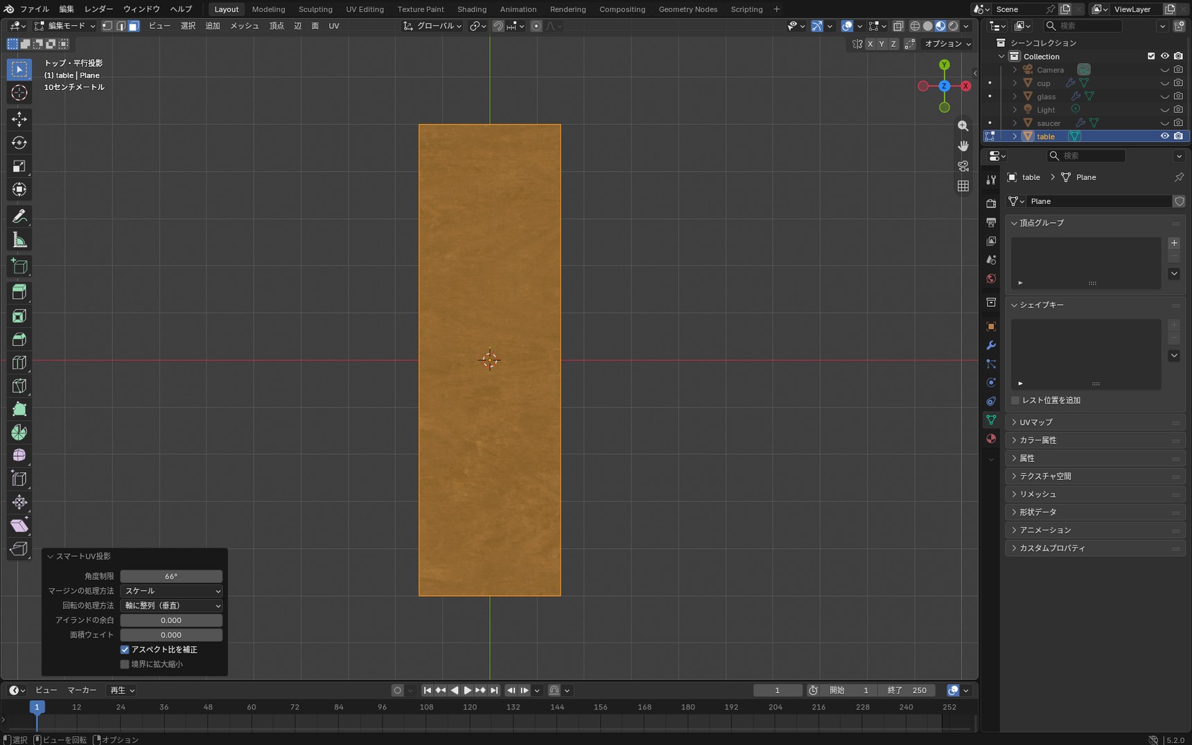
We'll use the wooden table built in the previous article, Blender Texture Basics: Base Color, Roughness, and Normal Maps. Making the tabletop longer changes its scale values, and the wood grain gets stretched lengthways. The previous article left it in that state.
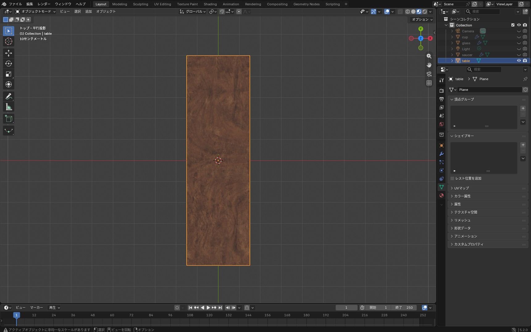
Applying the scale with Ctrl + A → "All Transforms" leaves the grain stretched. The scale values go back to 1, but applying the scale doesn't change the shape of the UVs.
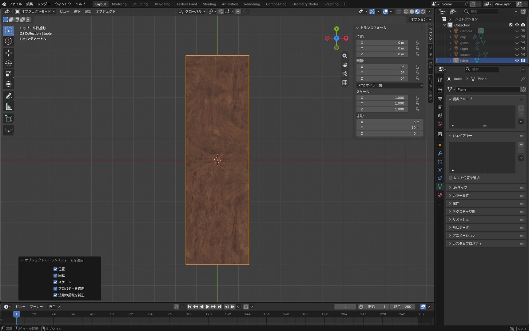
So we rebuild the UVs.
Running Smart UV Project
Select the tabletop, press Tab to enter Edit Mode, and press A to select everything. Press U and the UV Mapping menu opens.
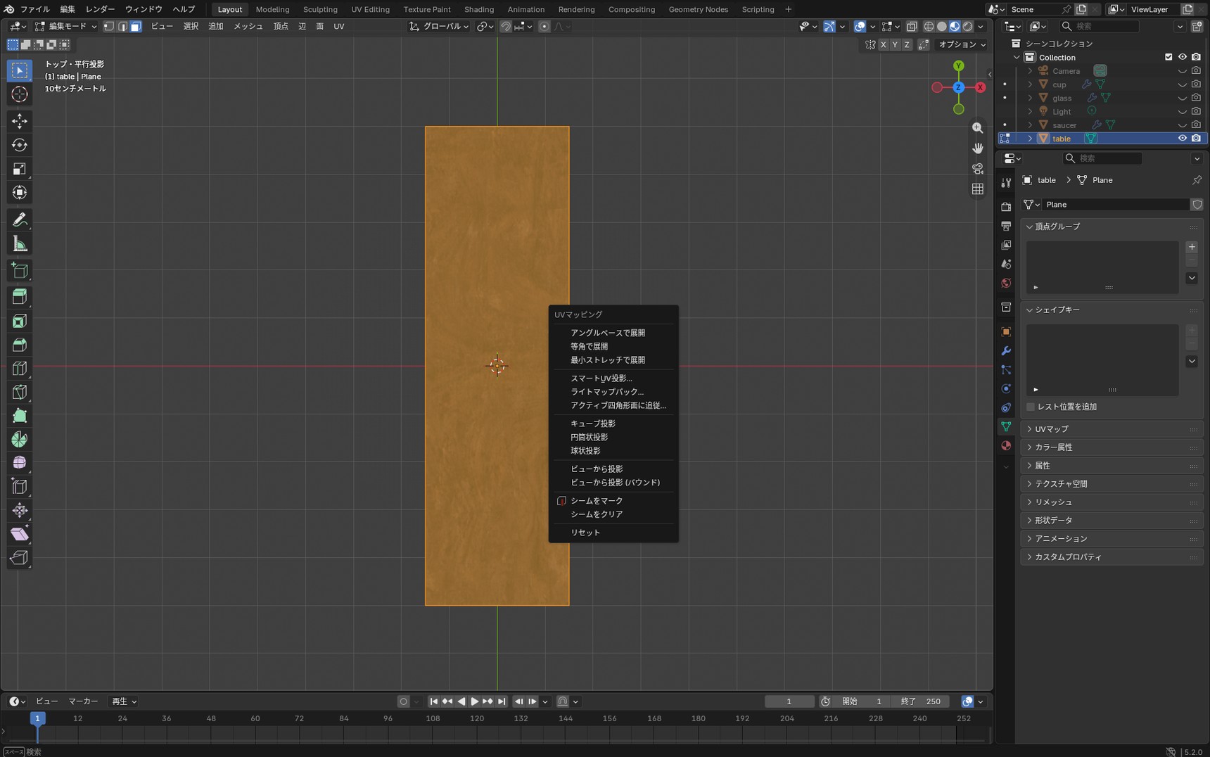
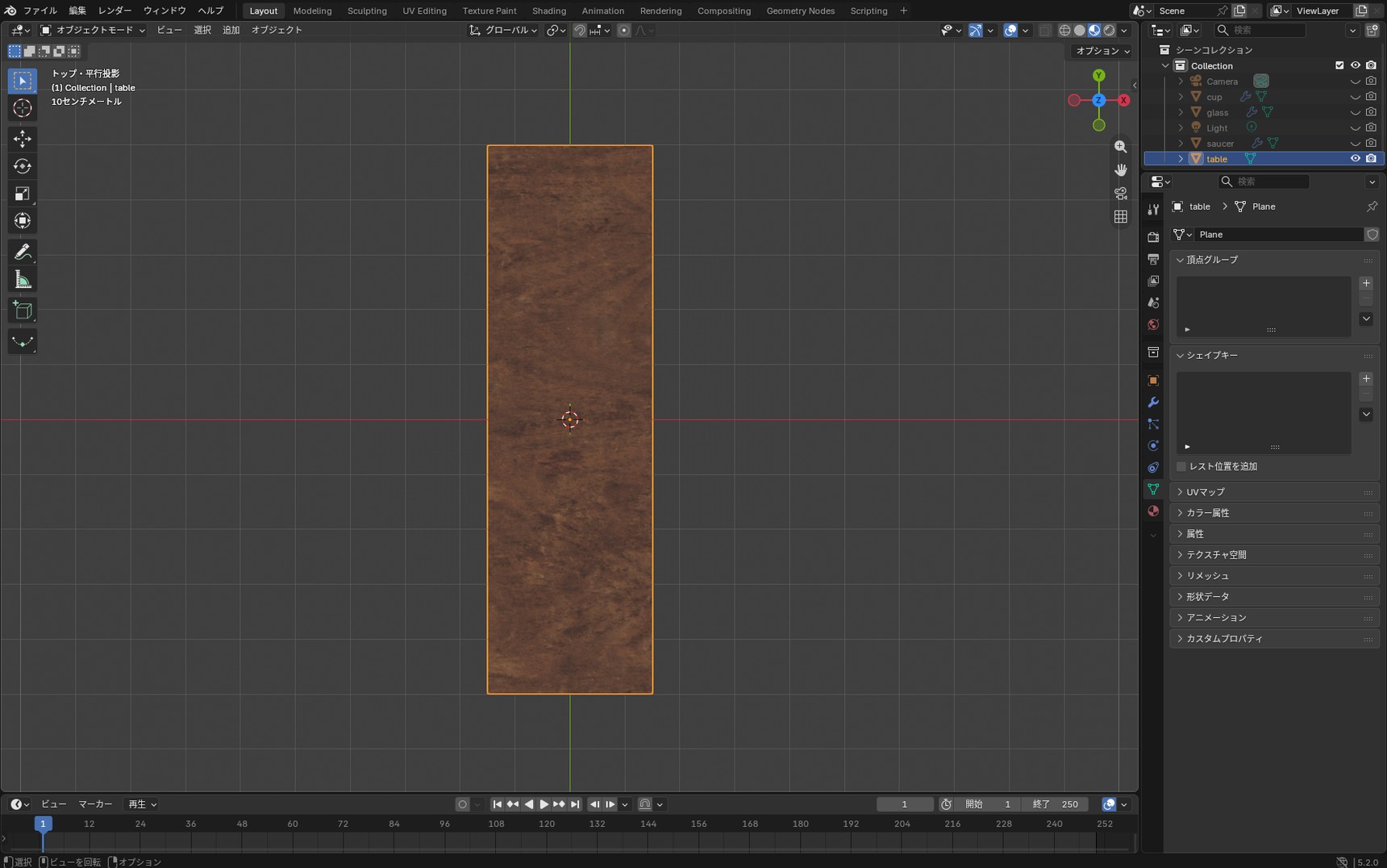
Choose "Smart UV Project" from the list. A settings window appears; leave it as it is and press "Unwrap".

The stretched grain is fixed.
Checking the distortion with a Checker Texture
Smart UV Project unwrapped it, but with a pattern like wood grain it's hard to tell whether the pattern is stretched or simply looks that way to begin with. So we temporarily apply an image of white and grey squares — a checker pattern — to find out. In Blender it's called a "Checker Texture".
In the Shader Editor, press Shift + A and add "Texture" → "Checker Texture".
- Connect "Color" on the Checker Texture to "Base Color" on the Principled BSDF
-
Connect a UV output to "Vector" on the Checker Texture. How you do that depends on the state of the material
- If an Image Texture is already applied: branch the output of the "Mapping" node feeding that Image Texture and connect it to "Vector" on the Checker Texture as well
- If nothing is connected yet: press Shift + A → "Input" → "Texture Coordinate", and connect its "UV" output to "Vector" on the Checker Texture
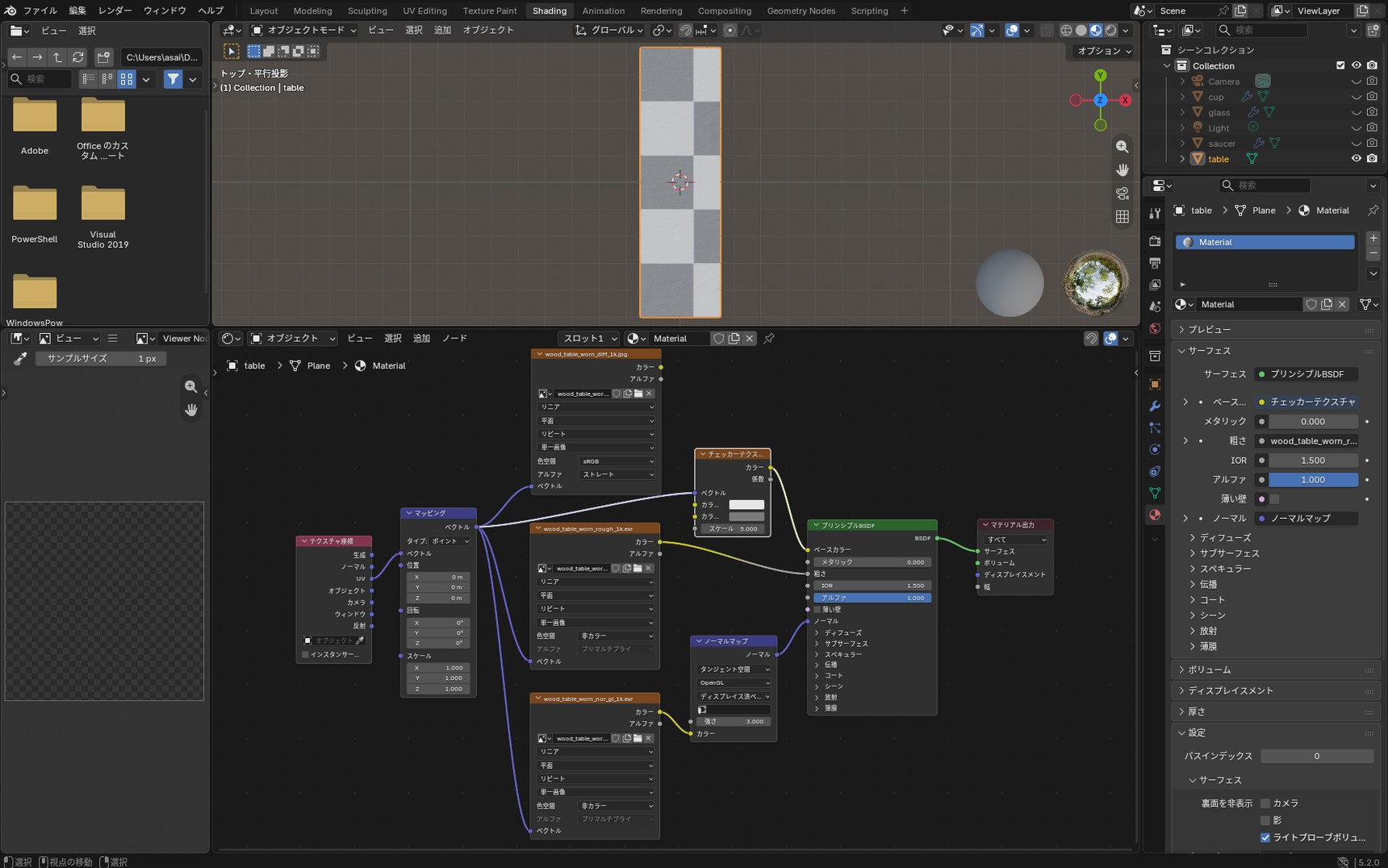
The Checker Texture doesn't read the UVs unless you connect them to "Vector". Without that, rebuilding the UVs won't change the squares.
An Image Texture reads the UVs with nothing connected at all, so it differs here.
Reading the shape of the squares
Once the Checker Texture is connected, look at the shape of the squares. Where they read as squares, the UVs aren't distorted. Where they read as rectangles, the UVs in that part are distorted.
Apply it to the cup and the saucer the same way. On the side of the cup the squares spread out sideways, and on the saucer their shape breaks up too.
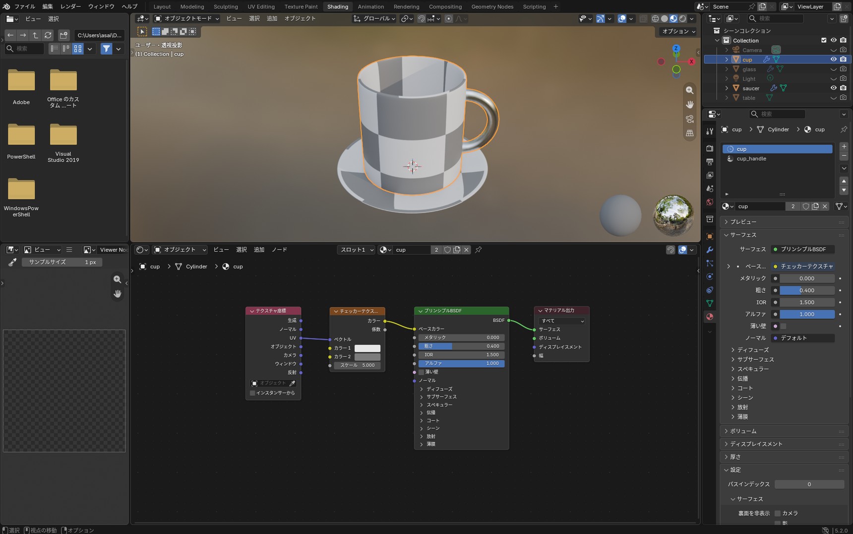
Set against the tabletop, the difference is clear. The tabletop has a grid of proper squares. Even within one scene the state of the UVs differs from object to object, so we check and fix them one at a time.
Once you've checked, connect the original Image Texture back to "Base Color". Only one link can feed "Base Color", so connecting the Image Texture disconnects the Checker Texture automatically.
When Smart UV Project isn't enough
The table was fixed by Smart UV Project alone. Next, let's run the same operation on the cup.
Select the cup, press Tab to enter Edit Mode, press A to select everything, and run "Smart UV Project" from U.
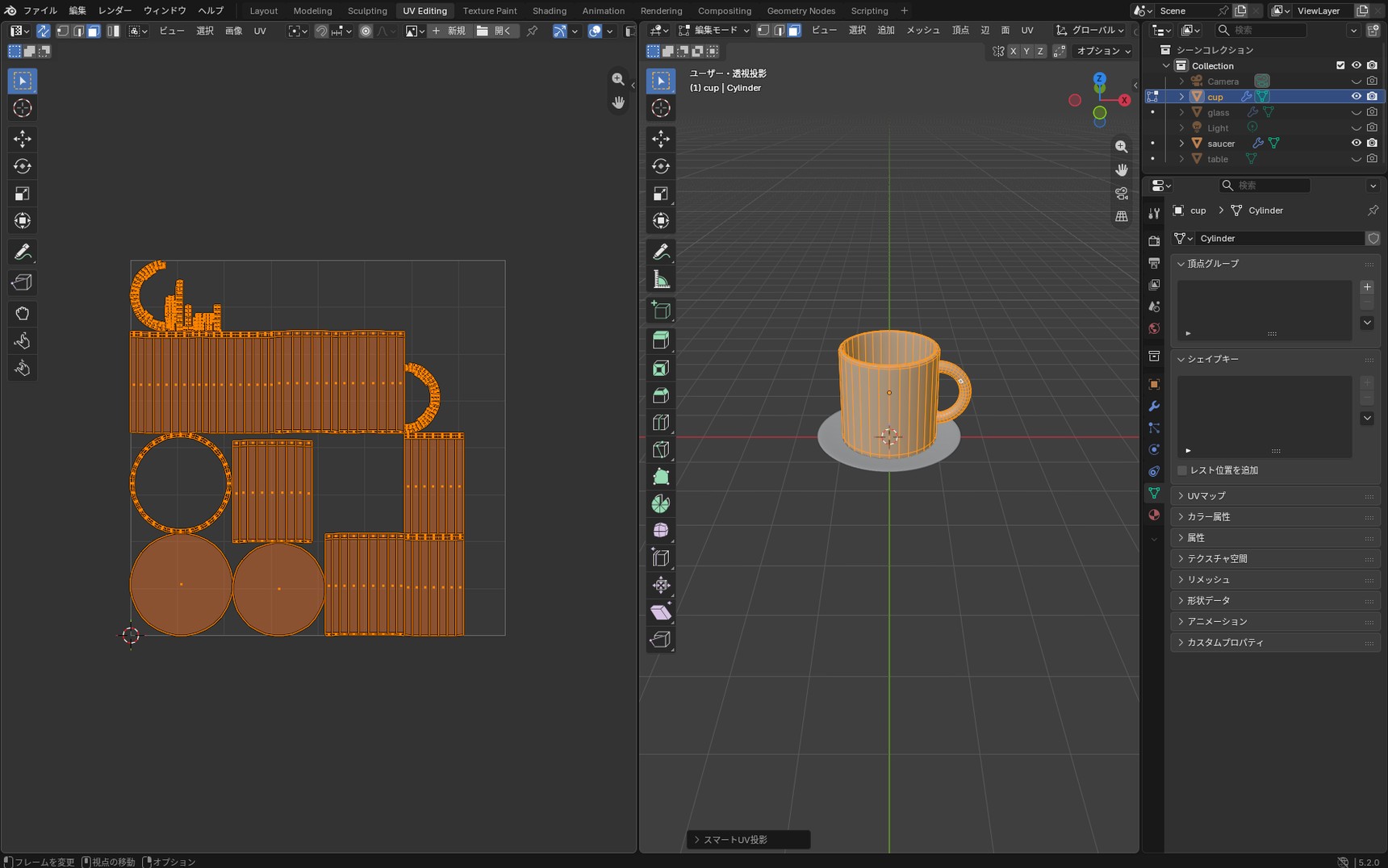
The side has been split into several bands. In this state there's no way to tell which part of the UVs corresponds to the front of the cup, so the logo can't be lined up with it.
Why it splits into bands
Smart UV Project looks at the angle between neighbouring faces and cuts where that angle changes sharply. The measure for that is the "Angle Limit" setting. The default is 66°.
On a cube, neighbouring faces meet at 90 degrees, which is over 66. That's a sharp change of angle, so a cut goes in along that edge.
The side of the cup is different. This cup's side is built from 32 segments, and neighbouring faces differ by only about 11 degrees. Nowhere exceeds 66 degrees, so no cut goes into the side.
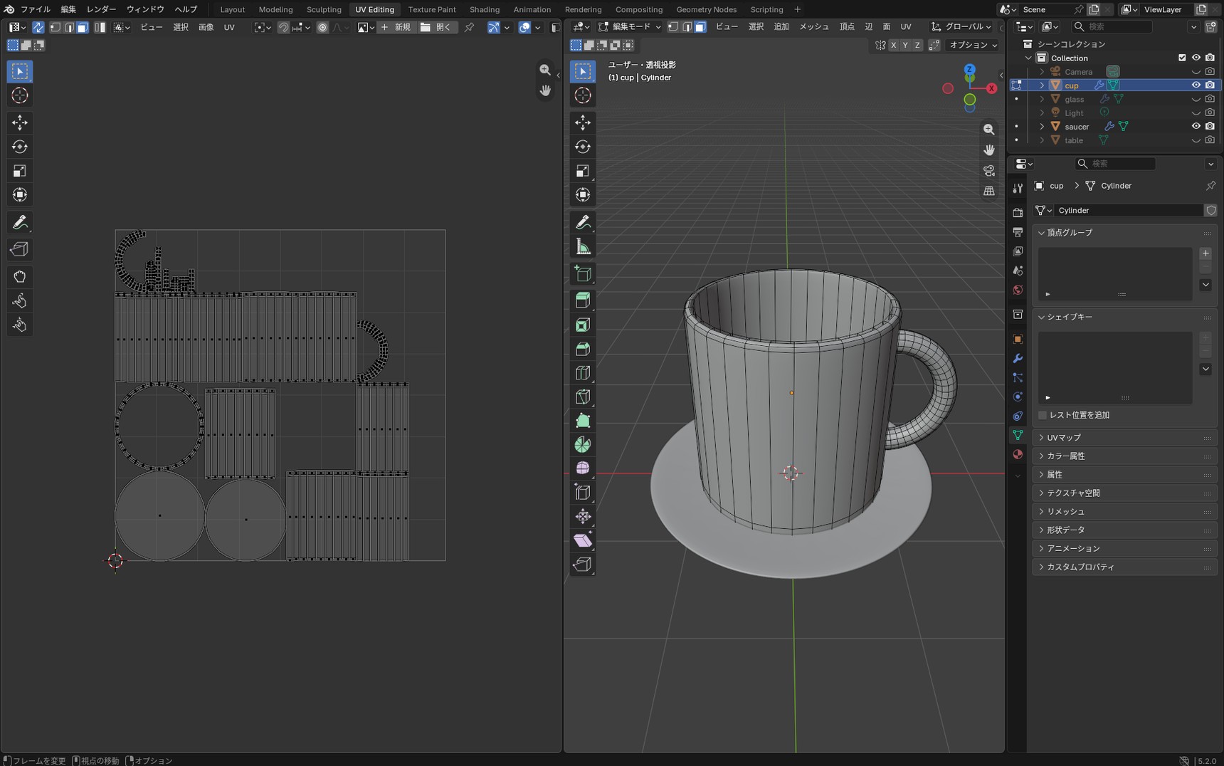
With no cut, it tries to flatten the cylinder as it is, and a cylinder won't lie flat on its own. The result is that the side ends up split into several bands.
For artwork with a set position, like a logo, use seams
All Smart UV Project looks at is the angle between one face and the next. It doesn't look at what the image shows, or at which side of the model is the front.
For an even pattern like wood, fabric, or concrete, Smart UV Project suits the job, because it doesn't matter to the look where the cuts land. Where you want a logo in a set place, as we do here, you decide the cuts yourself and unwrap the UVs.
Marking seams and unwrapping
We rebuild the UVs so the logo can go on the front of the cup. First, we decide where the cuts go. In Blender, a cut like this is called a "seam".
One vertical cut won't open out the side of the cup
Say you rolled a sheet of paper into a tube. To get it back to a flat sheet, you need one cut down its length. The side of the cup works the same way. Unlike a tube, though, the side of the cup is joined to the rim and to the bottom. Those joins have to be cut as well, or it won't come away as a single band.
That makes three places to cut.
- One vertical line at the back
- The ring at the rim
- The ring where the side meets the bottom
Unwrap with only the vertical line and the bottom, and the side doesn't come out as a band — it fans out into a wedge. Only once the rim is cut does the side come away as a single band.
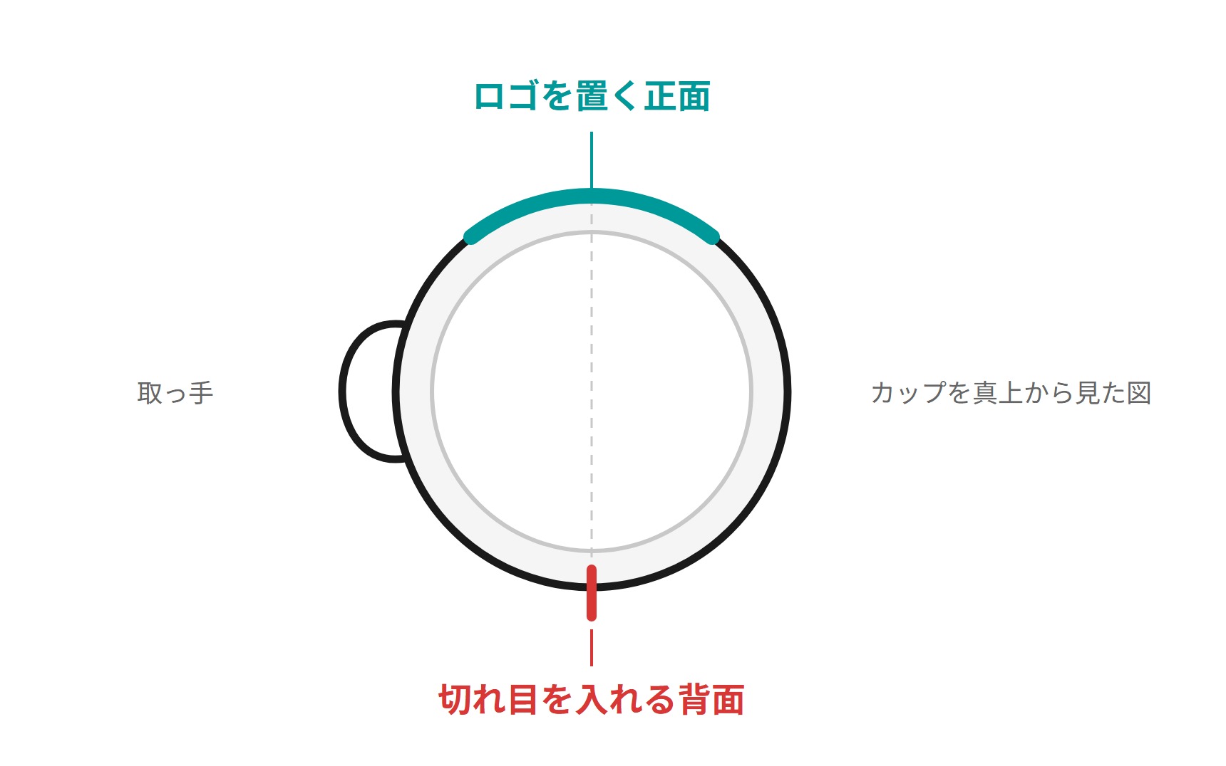
Put the cut on the opposite side from the logo
We're placing the logo on the front, so the cut goes at the back.
There are two reasons. The first is that an image doesn't carry across a cut. Put a cut down the middle of the logo and it splits into two separate halves. The second is that a join at the back is less noticeable.
Marking the seams
In Edit Mode, switch to edge select mode (2). Click the topmost edge in the vertical line at the back. Then hold Ctrl and click the bottom edge, and all the edges in between are selected together.
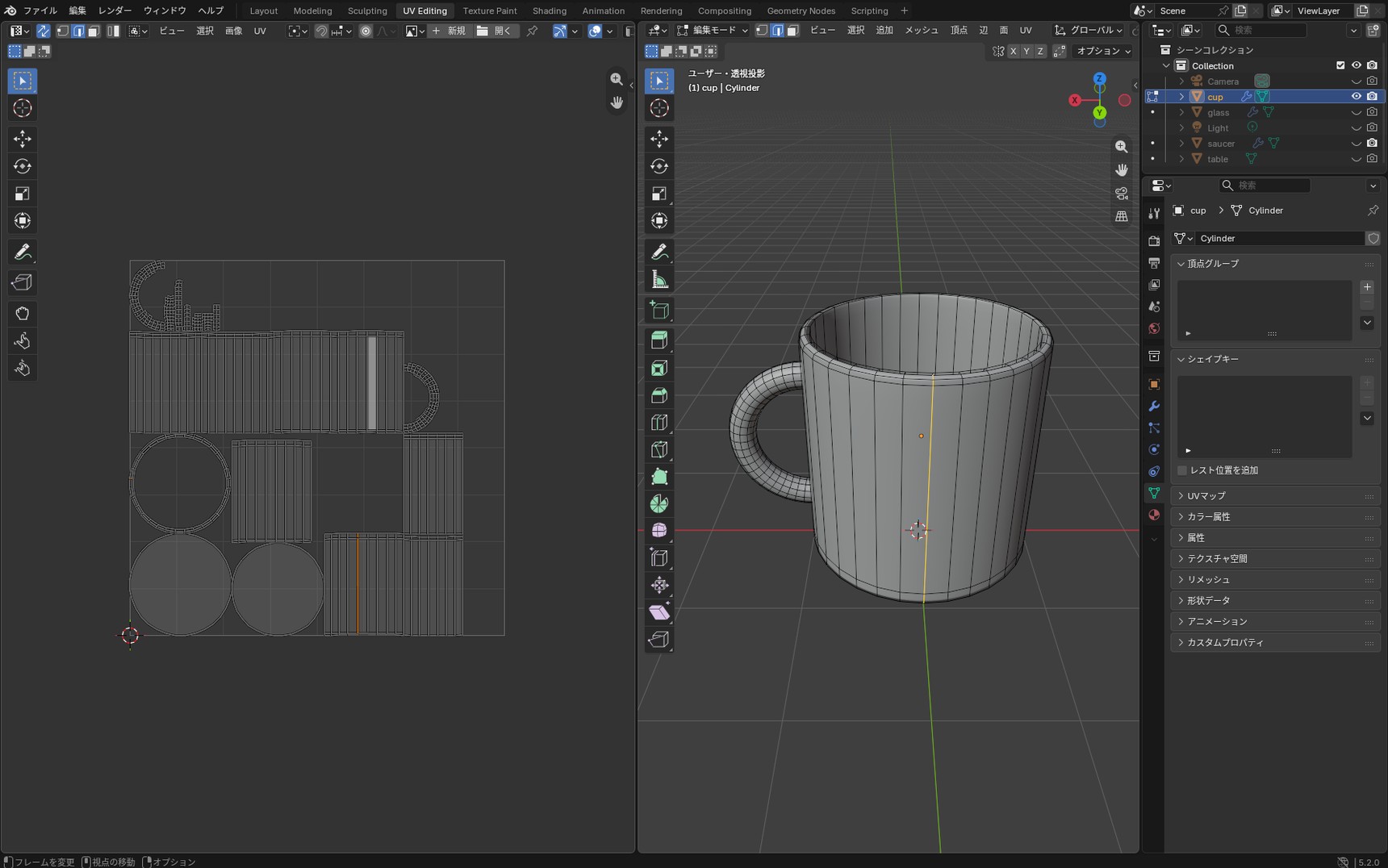
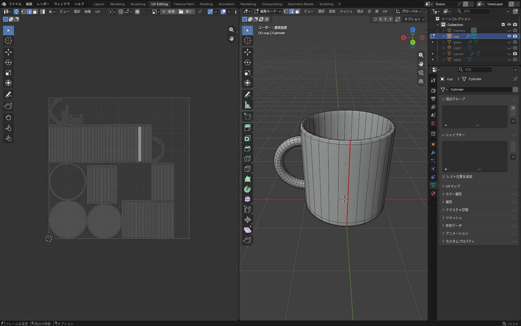
Press U and choose "Mark Seam". The selected edges turn red.
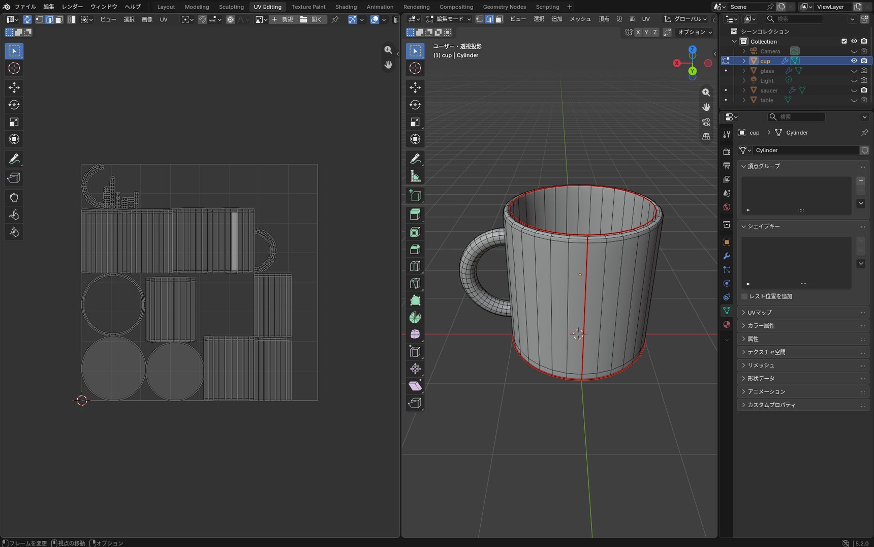
Next, mark seams the same way at the rim and where the side meets the bottom. These run as rings, so holding Alt and clicking an edge selects the whole loop at once.
Unwrapping
Press A to select everything, then press U.
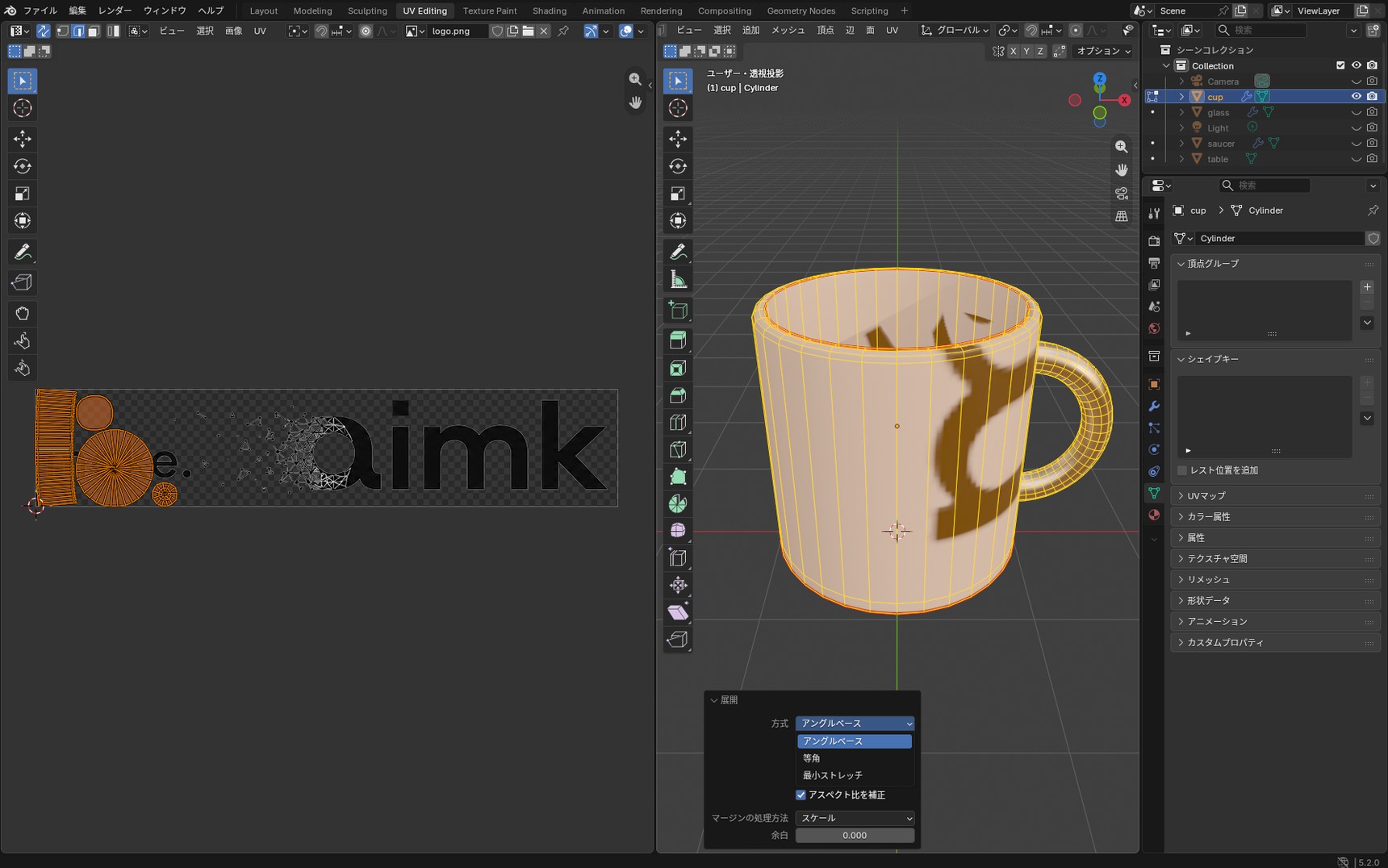
This used to be a single "Unwrap" entry, but the unwrap is now split into three methods.
- Unwrap Angle Based
- Unwrap Conformal
- Unwrap Minimum Stretch
Here we choose "Unwrap Angle Based". The differences between the three are covered in the column "The three unwrap methods", and unwrapping with the default is fine.
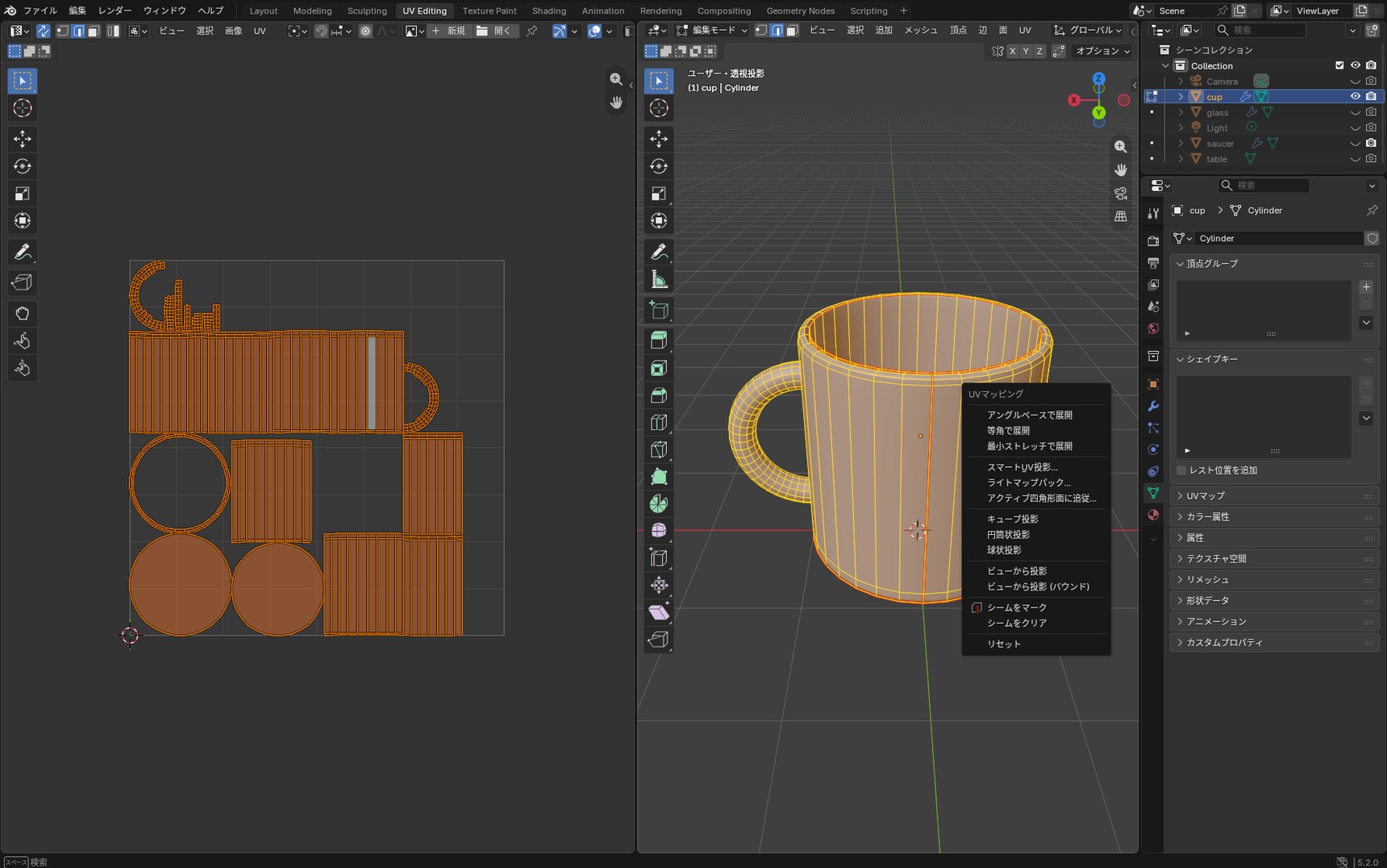
The side has opened out into a single band.
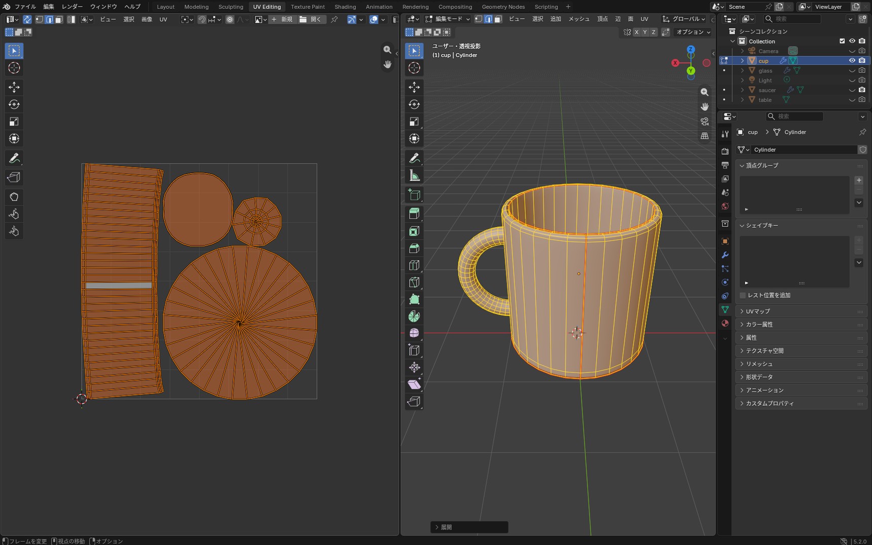
Before, the side was split across several bands; now it's in a shape where you can tell which part is the front. Alongside the band for the side, the bottom, the rim, and the handle each sit there as round groups. Groups like these are called "islands".
The band is still long and narrow. We'll sort out its size and orientation next.
Seams can be adjusted after unwrapping
You unwrap, and where something is stretched you add a seam, or take one away if there are too many. The official steps work the same way: mark seams, unwrap, then adjust based on the result.
The Checker Texture we used earlier works for this check too.
Fitting the logo to the front of the cup
Now we use the unwrapped UVs to put the logo on the cup. First, connect the logo image to the cup's material.
There are two things that trip people up here.
Connect it directly and everything but the logo turns black
In the Shader Editor, add an Image Texture node, open the transparent PNG of the logo, and connect "Color" to "Base Color" on the Principled BSDF. Everything that was transparent around the logo turns solid black.
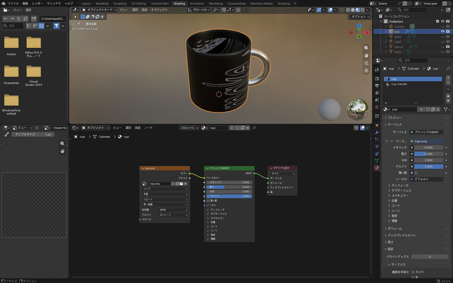
A transparent PNG carries the information about what's transparent separately from "Color". With only "Color" connected, that information never arrives, so those areas come out black.
Connect "Alpha" and now everything but the logo goes see-through
So let's pass the transparency information as well. Connect "Alpha" on the Image Texture to "Alpha" on the Principled BSDF. This time the transparent areas really do become transparent. Everything on the cup except the logo goes see-through, and you can see straight past it.
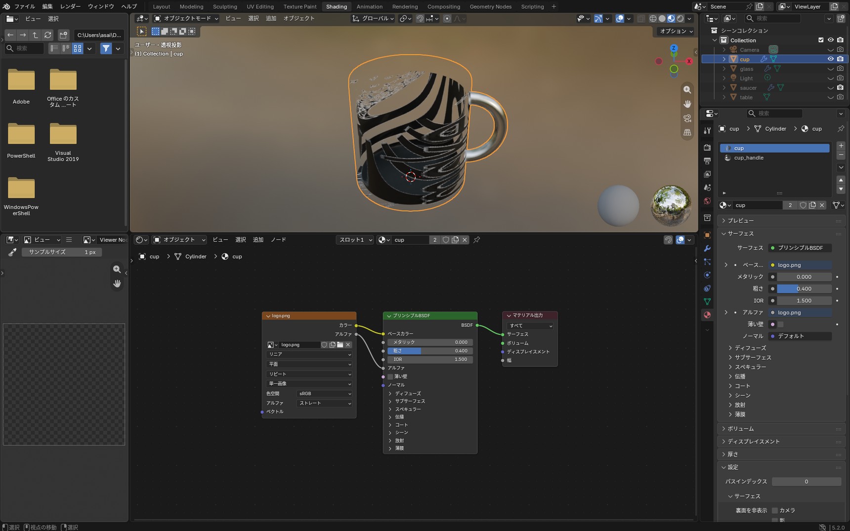
"Alpha" on the Principled BSDF is the setting that makes an area transparent. It isn't a setting for restoring the original colour, so everything but the logo going see-through is the correct behaviour.
Blending the cup's colour with the logo using Mix Color
What we want is to show the logo's colour where the logo is, and the cup's colour where it isn't. A Mix Color node does exactly that.
Press Shift + A, add "Color" → "Mix Color", and connect it as below. Once added, the node is labelled "Mix".
- Image Texture "Alpha" → Mix "Factor"
- Mix "A" → the cup's original colour (beige)
- Image Texture "Color" → Mix "B"
- Mix "Result" → Principled BSDF "Base Color"
Don't type a number into "Factor". Connect the alpha there and the areas with and without the logo are sorted between A and B automatically.
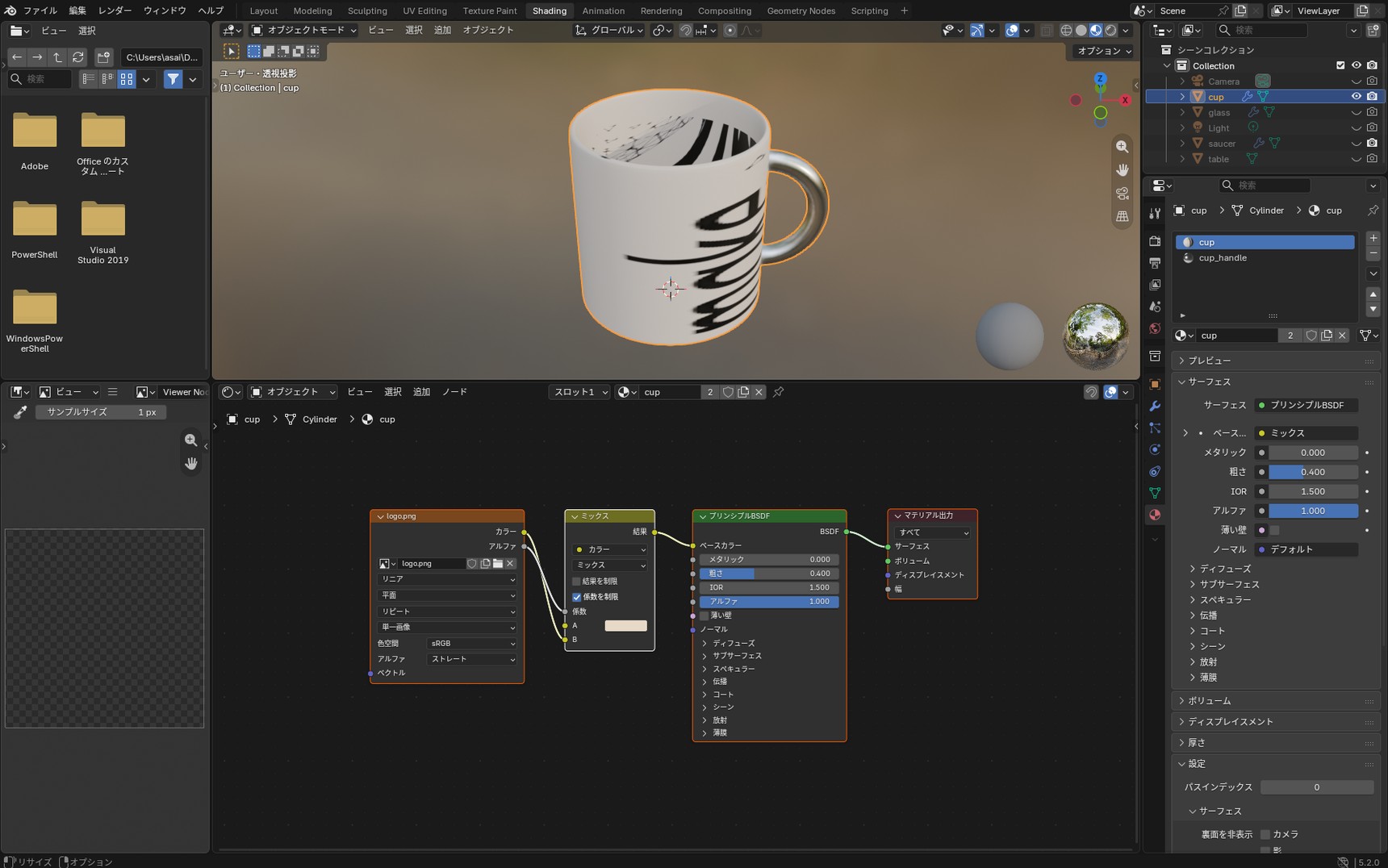
Now only the logo is applied, and the area around it keeps the cup's original colour. The sheen is intact too.
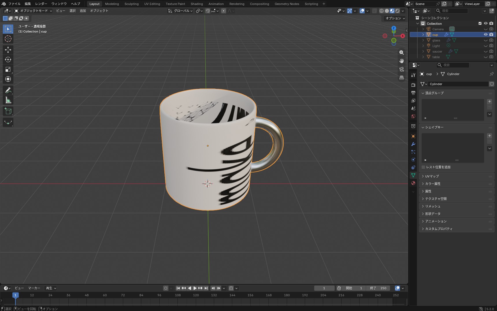
The logo is still distorted, though, and repeated all over the cup. We've settled how the colour comes out, but not the position and the size. From here we'll use the UVs to fit both.
Stopping the image from repeating
Before moving the UVs, there's one setting to change on the Image Texture node. Set "Repeat", third from the top on the node, to "Extend".
Left on "Repeat", the image tiles across and down whenever the UVs run outside it. While you're adjusting their position they run outside easily, and each time the pattern multiplies, which makes it hard to tell whether things line up. On "Extend", the colour at the edge of the image simply carries on outwards.
Moving the UVs to fit the logo
Click the image icon at the top of the UV Editor and pick the logo file from the list. The logo image appears underneath the UVs.
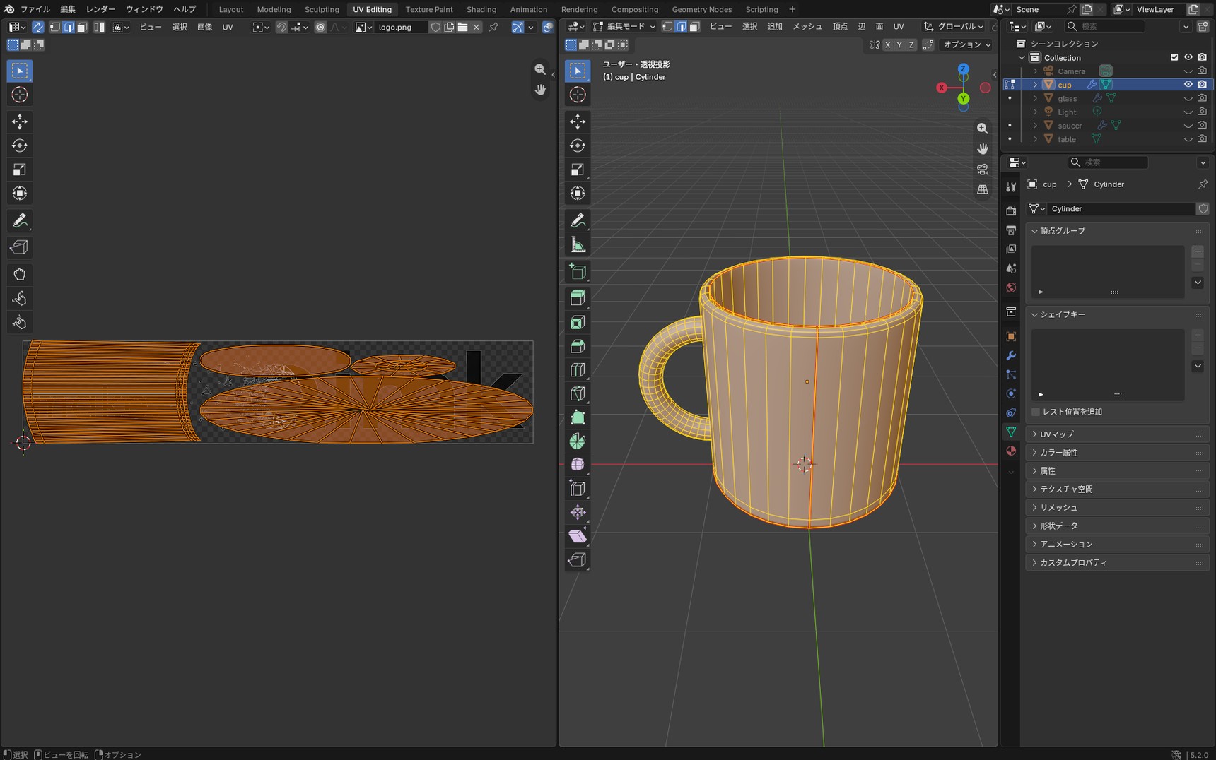
At this point the UVs and the logo don't line up. From here we move only the UVs for the side.
Hover over the island for the side and press L, and that group is selected. The islands for the bottom, the rim, and the handle sit there too, but L picks out the side on its own.
From there you move it the same way you would in the 3D Viewport.
- G: move
- S: scale
- R: rotate
These are the same operations used in the modelling article. They work as they are in the UV Editor.
Fit the position so the logo lands on the front.
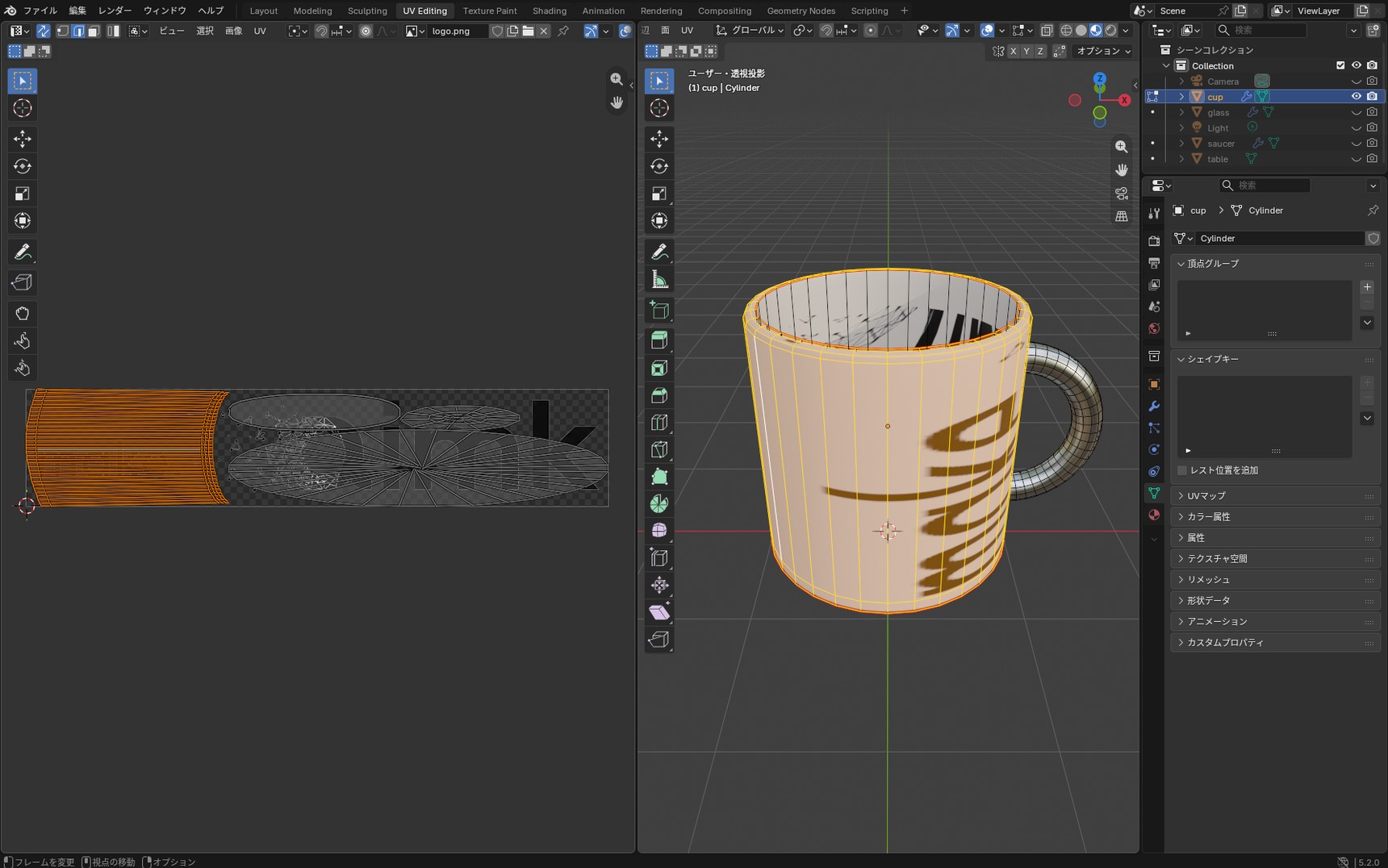
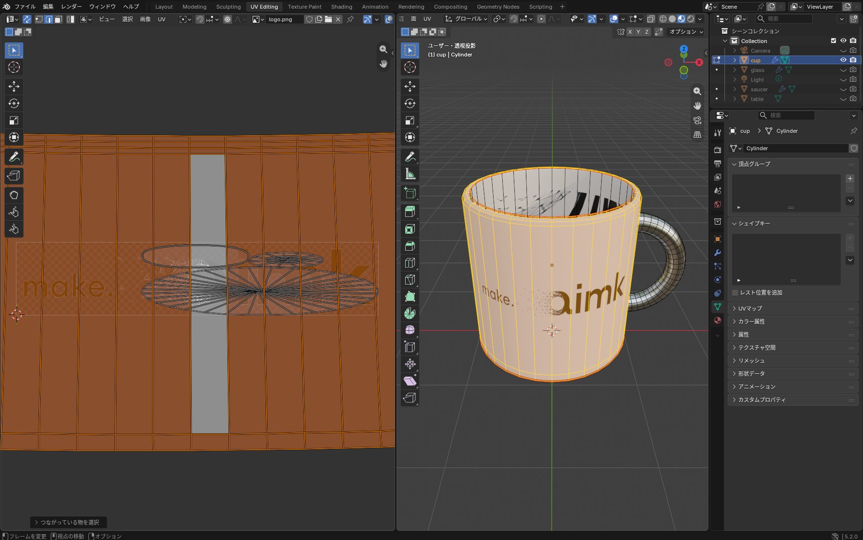
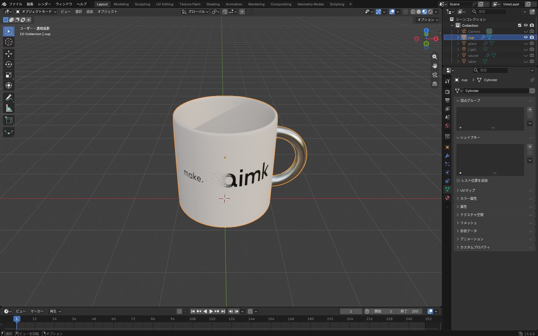
Check in the 3D Viewport and the logo is there on the front of the cup.
Checklist for when it doesn't work
When the unwrap doesn't come out as you expected, work through the following five checks in order.
- Is the scale applied?In Object Mode, run Ctrl + A → "All Transforms" and check that the scale reads 1. The order matters: apply it before you unwrap and the UVs are built at the right proportions. Applying it once the pattern has already stretched won't fix it, because applying the scale doesn't change the shape of the UVs. In that case, rebuild the UVs
- Are the faces selected?The unwrap works on the faces that are selected. UVs being visible on screen doesn't mean they're selected. Press A to select everything before running it
- Are any faces flipped?Faces pointing the wrong way can throw off the result of the unwrap. In Edit Mode, press A then Shift + N, and the faces are aligned to point outwards
- Do the UVs overlap?Where several UVs sit on the same spot, those faces will always show the same artwork. For applying an image, as we're doing here, overlap causes no problem. Overlap becomes a problem when you bake, the process of burning a pattern into an image
- Are the parts wildly different in size?The size of a UV translates directly into how fine the pattern is. Where two areas of similar size have UVs of very different sizes, the pattern comes out coarse on one of them
Checking UV distortion by colour
The Checker Texture was a way to check UV distortion from the 3D Viewport, with an image applied. The UV Editor has its own display for examining distortion.
Press the down arrow next to the "Show Overlays" button in the UV Editor header to open a menu. Tick "Display Stretch" in there.
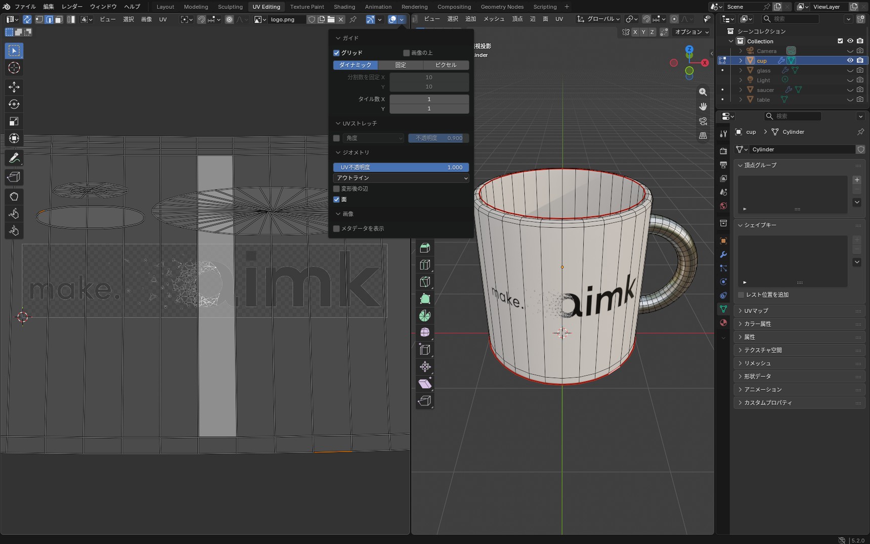
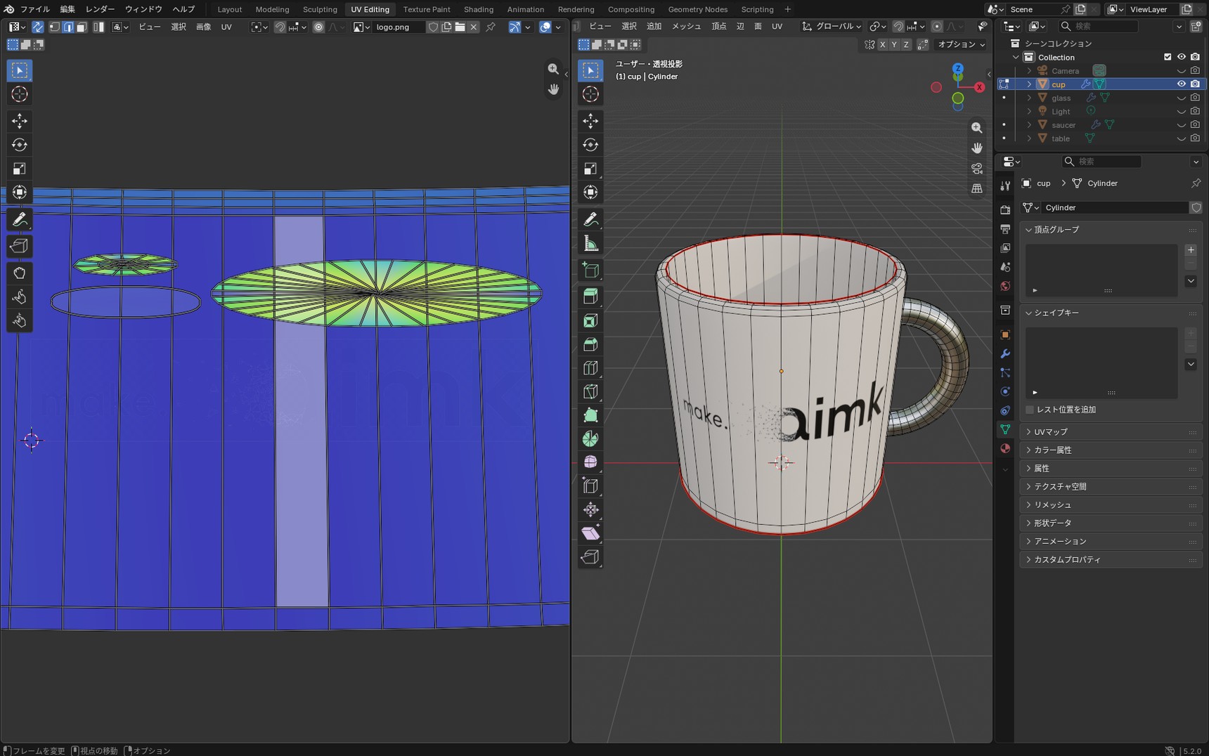
The closer to blue, the less the distortion; the closer to green or yellow, the more.
In the image above, the side we unwrapped with seams is a solid blue. The round islands at the bottom and the rim, on the other hand, read green to yellow, which tells you distortion remains there. Opening out a round face tends to break up its shape from the centre outwards. Where to start fixing is a decision you can make from the colours alone.
The method can be set to "Angle" or "Area". The default is "Angle", and that's the one to use for looking at distortion of shape. "Area" is for checking whether the islands are unevenly sized.
What comes next
The logo is on the cup. Once you can build UVs yourself, where the artwork goes becomes your decision.
If it feels like a lot to take in, these five points will get artwork where you want it.
- Try Smart UV Project first, and mark seams and unwrap when that isn't enough
- Smart UV Project cuts by the angle between faces, so a gentle curve breaks into several bands
- To get the side of a cup as a single band, cut in three places: one vertical line at the back, the ring at the rim, and the ring where it meets the bottom
- For a transparent PNG logo, connect the alpha to the Factor of Mix Color
- Check distortion with a Checker Texture and with Display Stretch
Next comes lighting. The same model can look completely different depending on how the light falls on it.
So far we've built the shape and the finish. What shows them off is the light.
FAQ
Q. My UVs look like a mess after unwrapping. Is that right?
A. Judge it by whether the pattern lands correctly, not by whether the UVs look tidy. Apply a checker image temporarily: if the squares read as squares, you are fine. Anywhere they read as rectangles, add a seam there or rebuild the UVs.
Q. Is it better to have fewer seams?
A. Fewer is not automatically better. Too few seams and the UVs stretch; too many and you get more visible joins. The measure is whether a seam is needed to open the surface out flat.
Q. Is it a problem if the UVs overlap?
A. Not for what we are doing here, which is applying an image. Sometimes you overlap them on purpose to reuse the same pattern across several faces. Overlap becomes a problem when you bake, the process of burning a pattern into an image.
Q. I don't want the logo on the inside of the cup or on the rim. How do I apply it to only some of the faces?
A. Move the UVs for the faces you want to keep clear outside the image frame. UVs placed outside the image pick up the colour at its edge. With a logo like this one, where the surrounding area is transparent, nothing gets applied outside the frame. To apply it to only some faces, fit just those UVs to the frame and leave the rest outside.
Q. If I adjust the UVs for the Base Color, will the Roughness and Normal images shift too?
A. They won't. All three read the same UVs, so rebuilding the UVs once re-applies all three to the new position. You don't need separate UVs per image.
Q. If I unwrap again, do I have to redo the image I already applied?
A. No. The material setup stays as it is, and the image is re-applied to the position of the new UVs.
Q. Do I have to apply the scale before unwrapping?
A. Applying it beforehand means the UVs are built at the right proportions. Applying it after the pattern has already stretched won't fix it, because applying the scale doesn't change the shape of the UVs. In that case, rebuild the UVs.
Q. Does marking a seam split the model open?
A. It doesn't. A seam is a mark that says cut here, and the shape of the model is unchanged. All that changes is how the UVs are divided.
Q. Nothing shows up in the UV Editor. Did the unwrap fail?
A. Most of the time it isn't a failed unwrap. If "Show Overlays" in the UV Editor header is off, the UVs exist but don't appear on screen. There's more in the column "When no UVs show up".
Columns
The three unwrap methods
The U menu lists three unwrap methods.
- Unwrap Angle Based
- Unwrap Conformal
- Unwrap Minimum Stretch
You don't need to press U again to compare them. Switch "Method" in the panel that appears at the bottom left right after unwrapping, and the UVs are rebuilt on the spot. That panel disappears as soon as you do anything else.
Try them on the same cup and the shape of the UVs visibly changes. With Conformal, the circle at the bottom is drawn out like a leaf. With Minimum Stretch it returns to a circle, but the lines bunch up towards the centre. The band for the side barely changes with any of them.
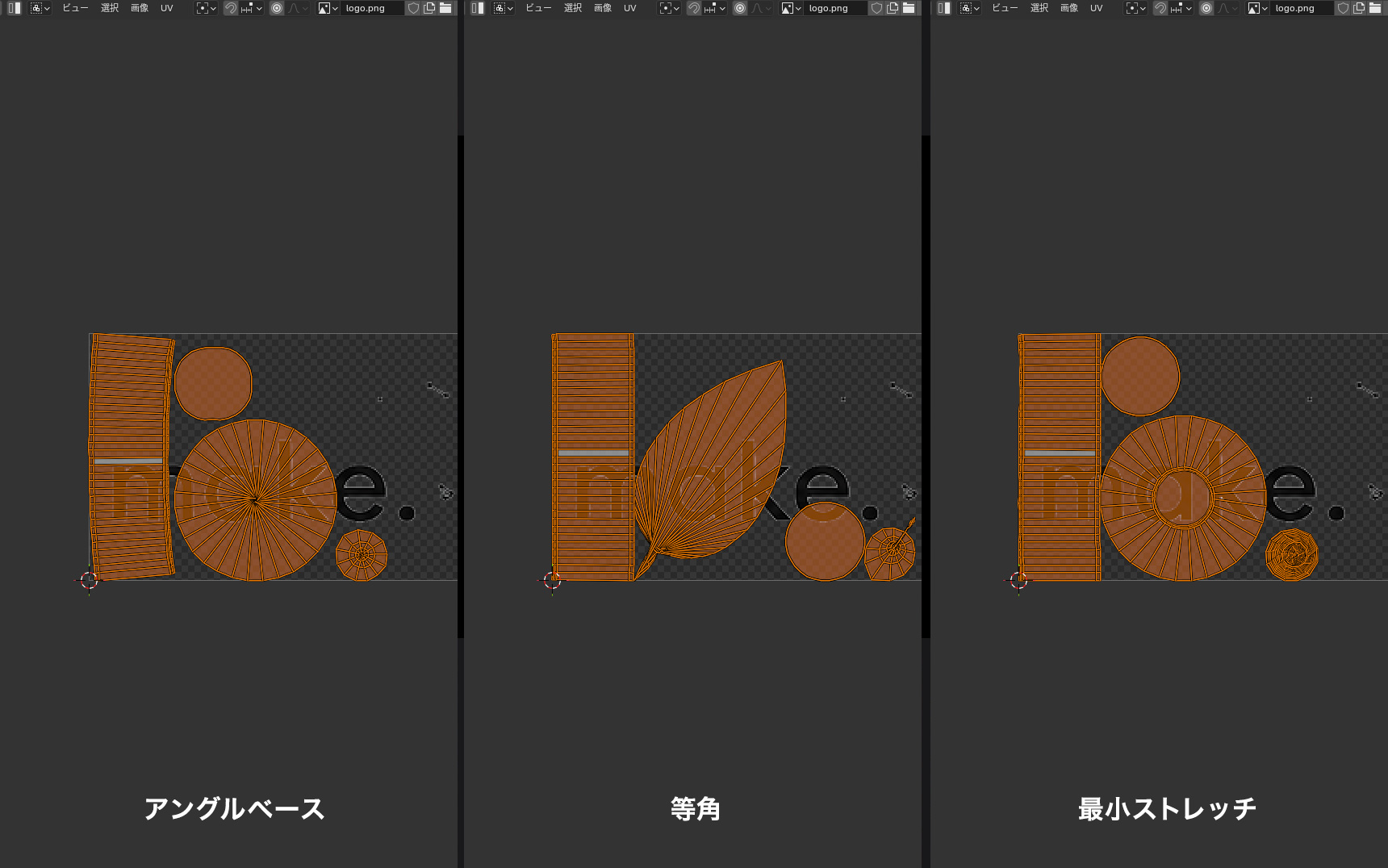
Apply a Checker Texture and compare in the 3D Viewport, though, and the squares look much the same. The UVs come out in different shapes, but there was hardly any difference in the result once applied.
Carrying on with the default, "Unwrap Angle Based", is fine. Unwrap once, and if the distortion bothers you, trying the other two for comparison is enough.
"Unwrap Minimum Stretch" alone shows different settings in the panel from the other two. There's an "Iterations" field, which tells you it's a method that reduces distortion by repeating the calculation.
What changing the Angle Limit does
The "Angle Limit" in Smart UV Project is the measure for cutting where the angle between neighbouring faces goes past that value. The default is 66°. You can check it by opening "Smart UV Project" at the
bottom left right after unwrapping.
Lower the value and even a slight difference in angle gets a cut. The UVs are divided more finely and each piece distorts less, but the image becomes harder to carry across them.
Raise it and cuts only go in where the angle changes sharply. The UVs come out in larger groups, but forcing them flat makes stretching more likely.
Using the default and adjusting as needed, based on the result, is the way to keep this straightforward.
For a single logo, there's another way
The U menu has an entry called "Project from View". It builds UVs straight from the direction you're currently looking at.
Run it with the cup viewed from the front (numpad 1) and you get UVs with no distortion at the front, without marking any seams. From there you fit the size and position to the logo, as in the main article. It saves you the seam-marking steps, but the fitting is still needed.
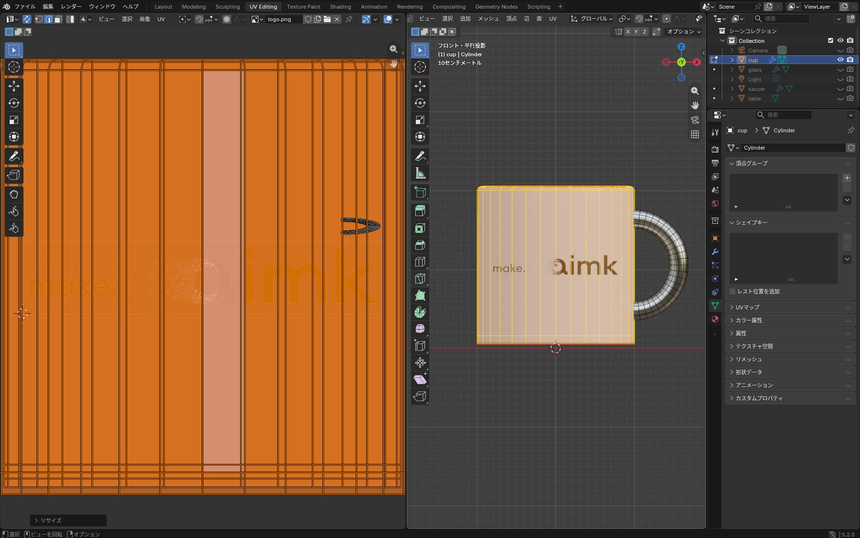
Look at the UV Editor at this point and the silhouette of the cup has become the shape of the UVs, because it's tracing the shape as seen.
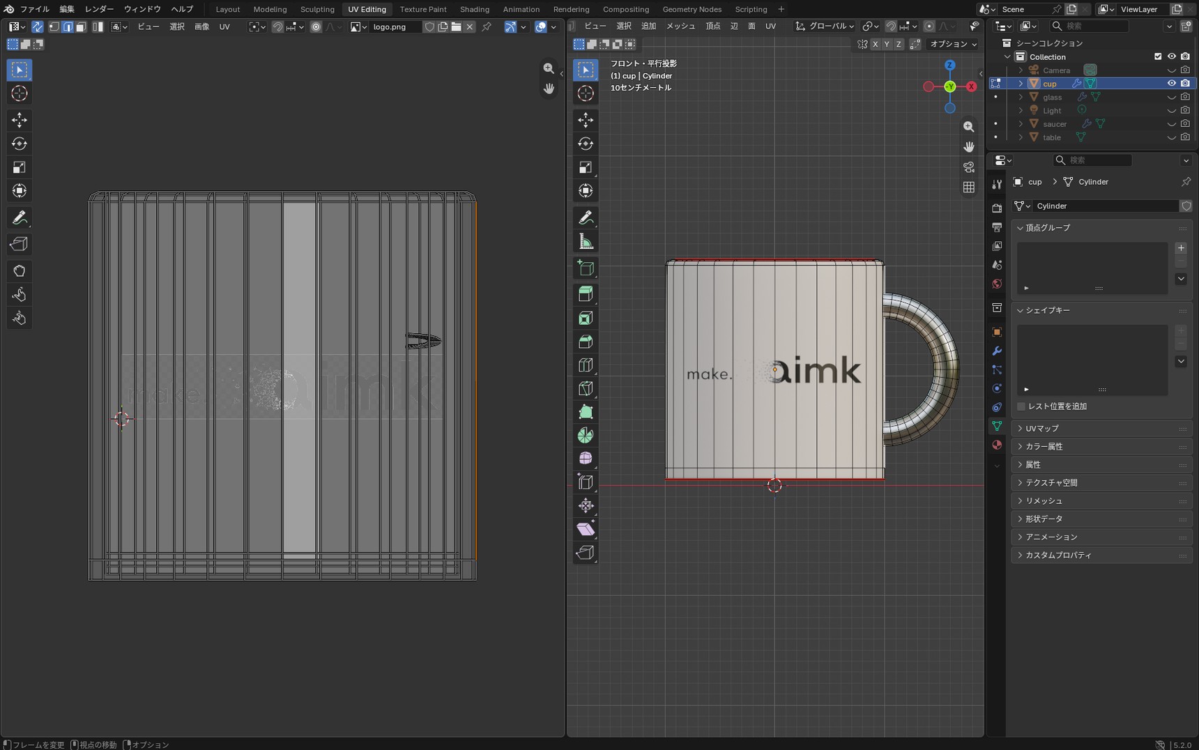
It only holds up from that one direction
Turn the cup to the side and the artwork breaks up.
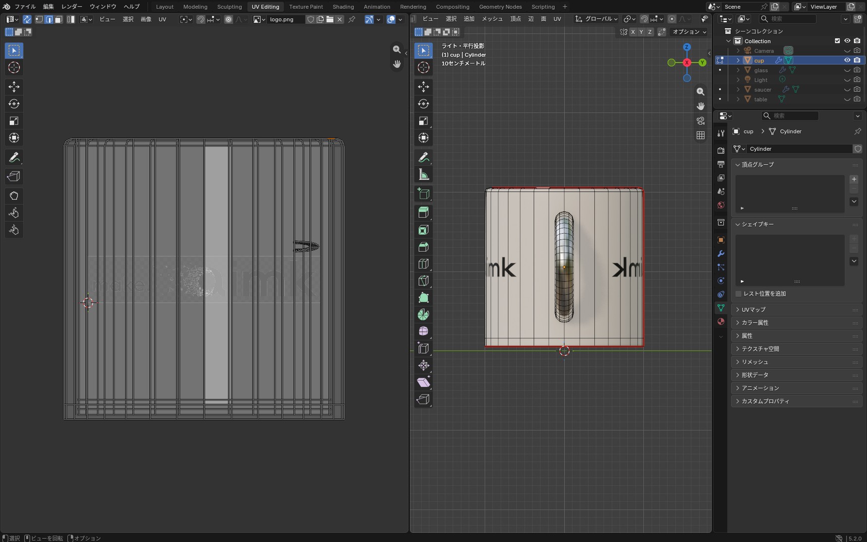
That's because it shines a light from the front and traces the shape like a shadow puppet. The side runs almost parallel to the direction of projection, so the narrow strip visible from the front is stretched across the whole side. It's mirrored left to right because the near and far faces land on the same place in the UVs.
Where the front is the settled view, or where you want a single image on a flat surface, it's a quick way to work. Where you'll turn the model to show it, though, or want a pattern over the whole thing, you need to mark seams and unwrap the UVs as in the main article.
When no UVs show up
Sometimes nothing appears in the UV Editor even after you enter Edit Mode. It looks as though the unwrap failed, and switching the select mode, toggling "UV Sync Selection", or framing everything makes no difference.
In this case the cause isn't the UV unwrap: it's that "Show Overlays" is off. Enable that button in the UV Editor header and the UVs appear.
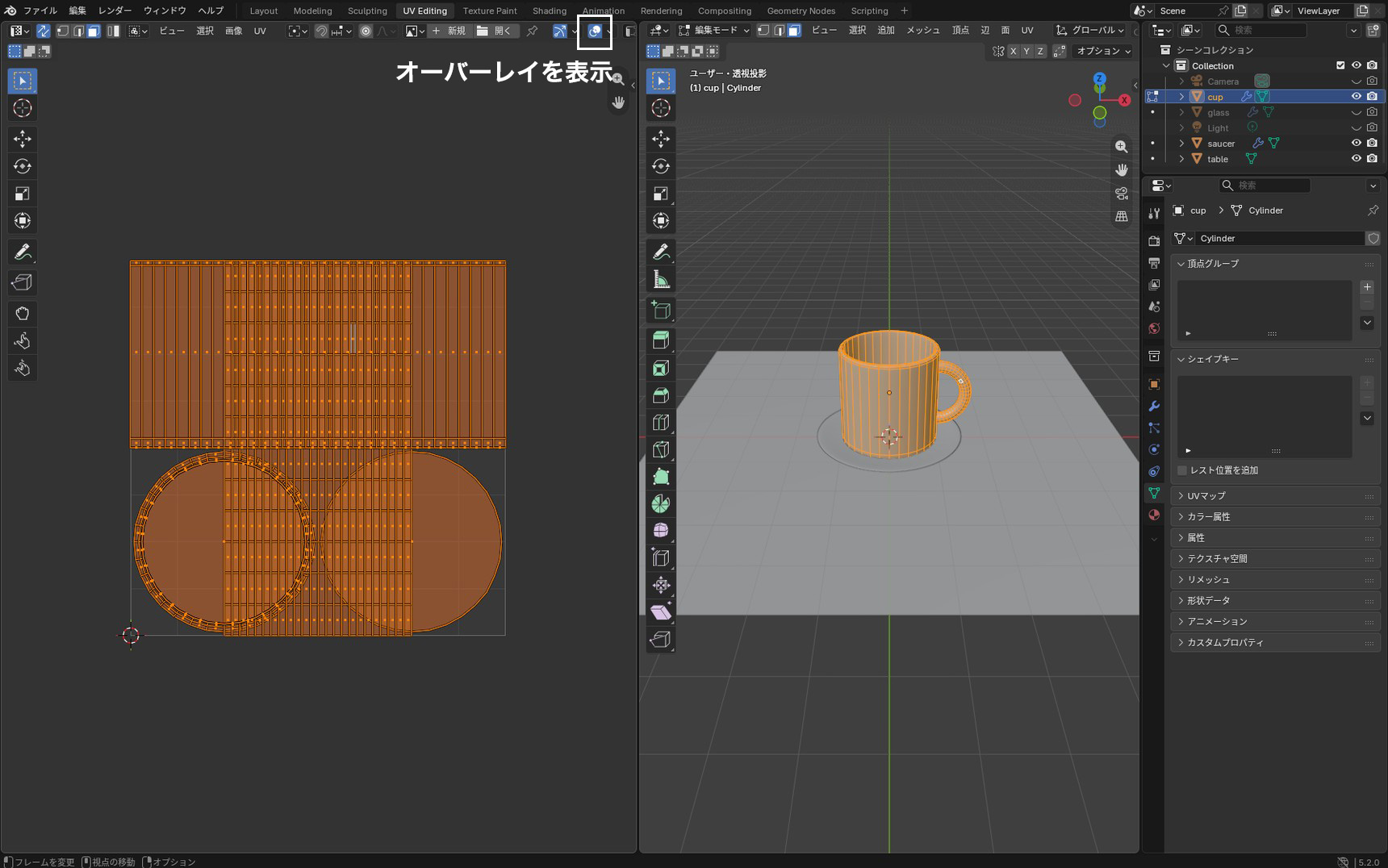
The UVs can also end up off screen when you switch which image is displayed. For that, "View" → "Frame All" (Home) brings them back.